Uncertainty in the predicted lifetime of load-bearing mechanical systems in consequence of functional impairment or collapse will be controlled by autonomous approaches of structural health monitoring and control. Hence the system’s behavior is monitored and integrated actuators are used for structural control. Load-bearing structures in mechanical engineering applications typically face the challenge of withstanding and transmitting external loads. In most cases, the load path through the load-bearing structure is predetermined by the design. However, if parts of the load-bearing structure become weak or suffer damage, e.g. due to deterioration or overload, the load capacity becomes uncertain. An approach to bypass a portion of the loading away from damaged parts of the structure used in order to prevent the structure from failure or malfunction is semi-active load redistribution.
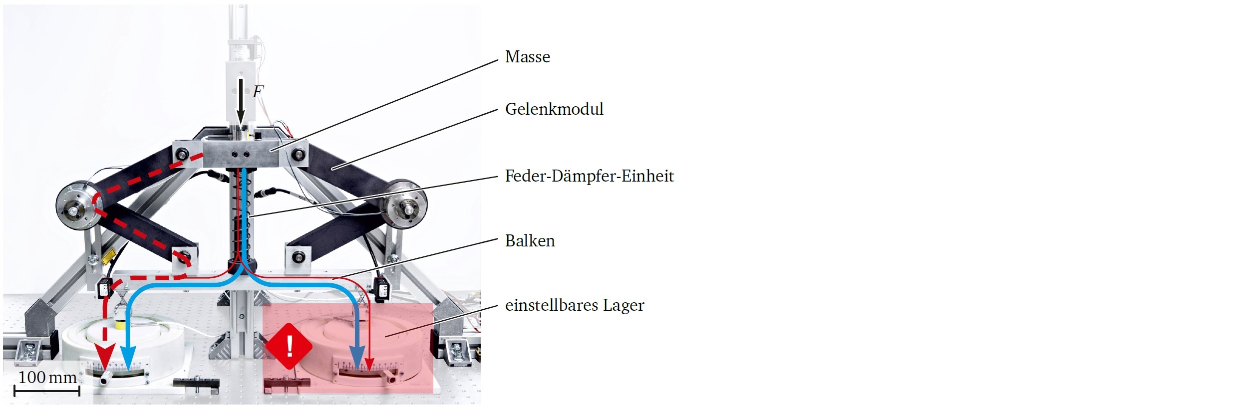
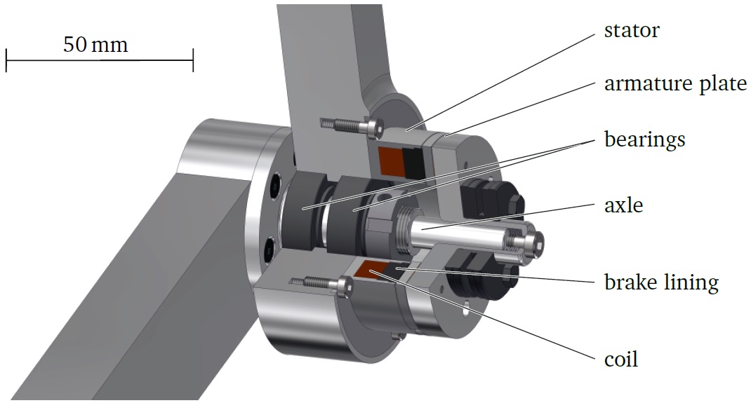
The structure to investigate semi-active load redistribution, see Figure 1, is based on a load-bearing structure developed within the Collaborative Research Center 805 and consists of a translational moving mass connected to a beam by a spring damper and two newly developed semi-active augmented guidance elements for load redistribution (see Figure 2). The stiffness characteristic of the beam’s supports can be adjusted to simulate structural damage. In turn, the structural damage causes a misalignment of the beam, which is defined as malfunction. The proposed semi-active load redistribution provides a technological possibility to influence the load path during operation via augmenting already existing parts of the load-bearing structure with actuators.
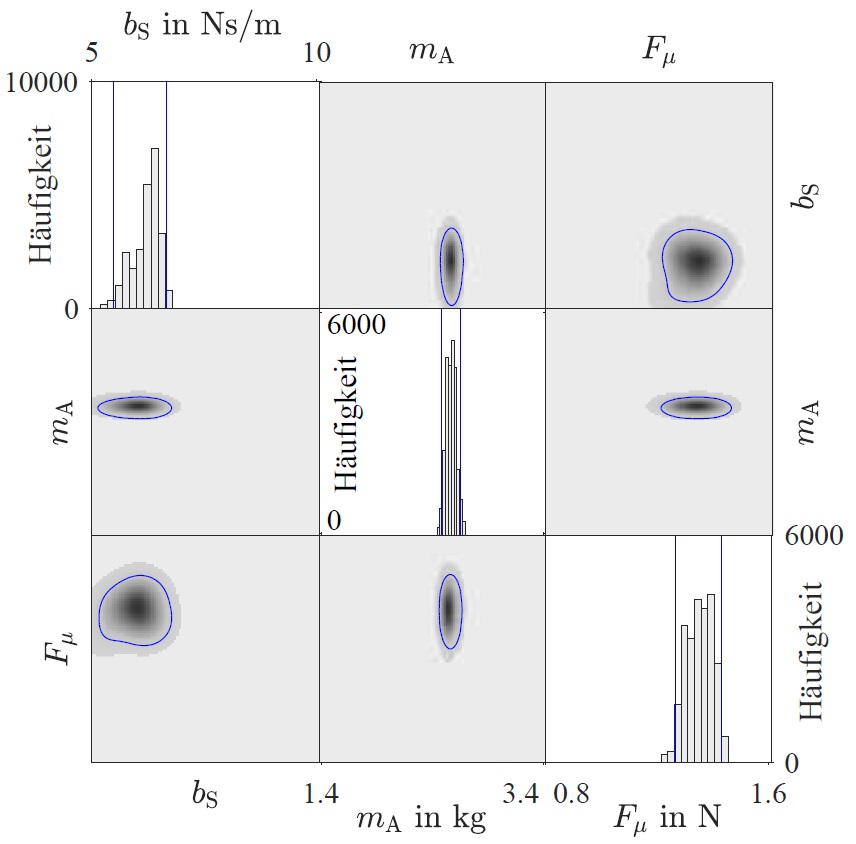
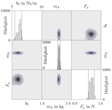
For accurate numerical predictions of the load redistribution capability, an adequate mathematical model is indispensable. Therefore, the credibility of the load-bearing structure’s mathematical model predictions is evaluated and increased methodologically by model parameter uncertainty quantification and reduction. A Bayesian inference based stochastic calibration procedure is applied to reduce and simultaneously quantify the model parameter uncertainty (see Figure 3). Thus, the model is adjusted to the present conditions and the model prediction accuracy is increased.
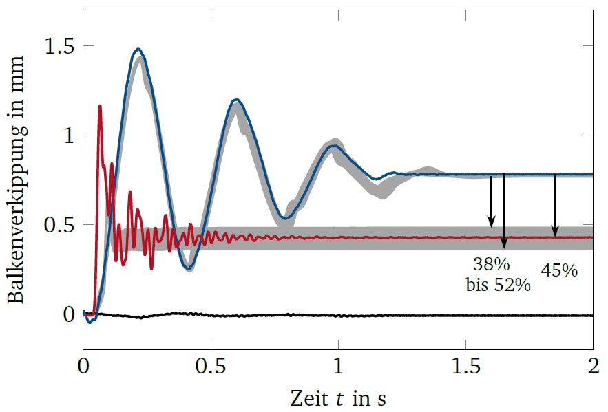
Comparing the passive and semi-active load-bearing structure, the malfunction is reduced by up to 52% numerically and by 45% experimentally. The semi-active guidance elements achieve a redistribute of the load between the two supports of the beam. The uncertainty of the model prediction is taken into account by Monte Carlo simulations and visualized via uncertainty areas (see Figure 4). This results of sub-project C7 of the collaborative research center 805 contribute to the methodological parameter uncertainty quantification and reduction as well as the technological application of semi-active load redistribution.
Contact: Dr.-Ing. Christopher Gehb